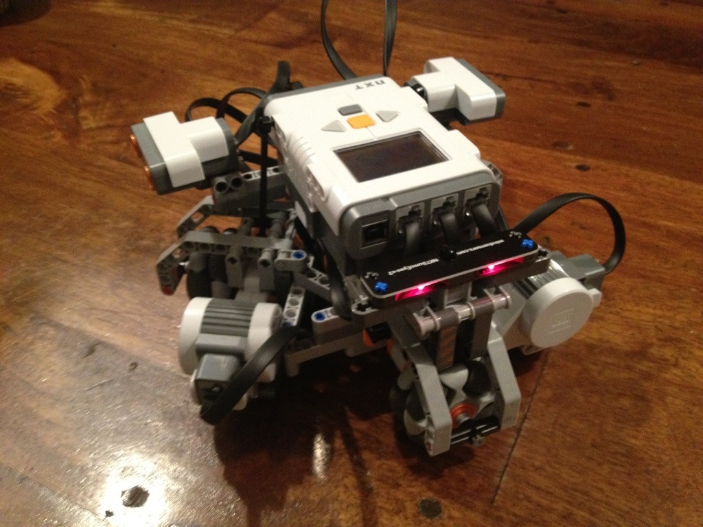
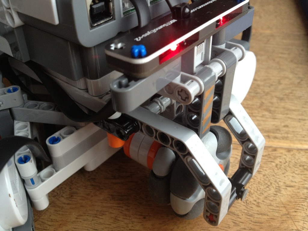
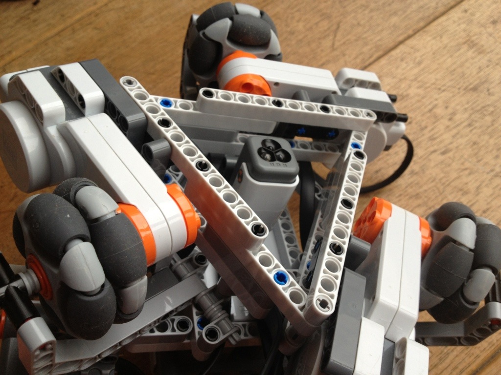
Recently i build a three wheel robot using mindstorms and Mindsensors NXT Sumoeyes Infrared sensor35. The wheels are HiTechnic RotaCaster omniwheels 31. I programmed the bot using RobotC for Mindstorms.
 |
 |
 |
| After years the new ZX Spectrum Online database is ready. The new database contains 18962 records. Al programs are online playable without the need of any plugin. Just an up-to-date browser is enough. Its not tested on IE.. but why should I. IE sucks anyway.! Firefox rulez |  |
I used a 3mm white acrylate frame. I had it made using laser cutting technology. There are a lot of companies on the internet selling these services. You need to make an design using Autocad. This is the design I made. ( ipad-frame1-2007.zip ) You can open the design in Autodesk Autocad 2007 or compatible app. After installing it all, the result is superb! A multifunctional console to control all devices in the house and also play mp3 music to the stereo….
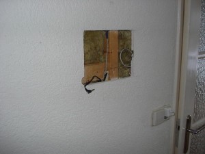 |
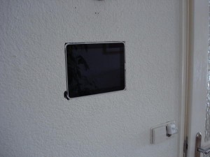 |
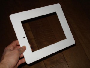 |
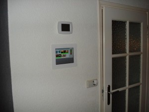 |
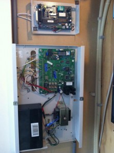
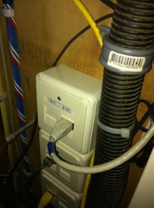
I started my domotica project a couple of month ago. I wanted to be able to control all my home equipment using my iphone or my ipad. First of all I had to select a domotica standard to use like Z-wave and X10. I selected the X10 standard because this is one of the oldest standards and there is a lot of X10 compatible stuff to buy out there. Marmitek is market leader when it comes to X10 devices. The X10 protocol is used for the signals over the existing powerlines in a home. A X10 devices has a unique house en device code like for example A02 and B03. I wanted a couple of DIN X10 devices in my meter cupboard to control the lights in the garden. This resulted in a expansion of my meter cupboard because I also needed 3 phase coupler modules to send all the X10 signals from one phase to the other.
 |
 |
 |
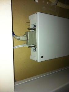
The RS232 Interface uses a null modem to connect to the computer. You need a cable with a DB25 onnector and in my case a DB9 connector. These are the pins needed for a connection between the computer en the E054 interface.
Good documentation of the RS232 interface is hard to find. So here is the pin layout of the cable I used:
DB25 DB9
---------------------------
pin2 ---- pin2
pin3 ---- pin3
pin5 ---- pin7
pin7 ---- pin5
I connect using a baudrate of 19200 baud. All other speeds did not work in my case. This is strange because in all documentation I found in the internet a speed of 9600 baud (8 bit, 1 stopbit an no parity ) is
mentioned. However.. 19200 baud works and is even faster… still nothing compared to my gigbit ethernet
Now I’m able to use the Galaxy Gold with my Iphone4 using Jaadu RDP to connect with the virtual machine. Of course you can use any RDP client you want to connect. Yooohooo… mission accomplished !
You need to define your ServiceURL in your config-file (SEP0xxxxxxxx.cnf.xml) of your 7970 iphone.
<servicesURL>http://192.168.8.6/menu.xml</servicesURL>
In this file you can define the menu for your services button.To publish the cam script use this code:
<CiscoIPPhoneMenu>
  <Title>IPAS XML Services</Title>
  <Prompt>Please make your selection.</Prompt>
  <MenuItem>
    <Name>Axis Netcamera </Name>
    <URL>http://192.168.8.6:/cam.php</URL>
  </MenuItem>
</CiscoIPPhoneMenu>
This is the actual php script wich generates the xml output and shows a png-image converted from an image of your Ip-camera. The script supports 4 different cameras and softkeys.
I created the script for use with apache and ImageMagick on linux. It is important that you have the php-pecl-imagick modules installed in your apache. This module is needed to convert the jpeg-image to png format and resize the image to match the 7970 browser. Remember to edit the variables in the script to your need.
<?php
////////////////////////////////////////////////////////////////////////
// IP-Camera image on your Cisco 7970G IP-phone
////////////////////////////////////////////////////////////////////////
// This simple script downloads an image from your ip-camera (Axis) and
// convert the image to a 7970G browser format.
// Script by ipas 27-10-2012
////////////////////////////////////////////////////////////////////////
// You need php-pecl-imagick installed on your apache-server
////////////////////////////////////////////////////////////////////////

$camurl1="http://cam1.domain.com/axis-cgi/jpg/image.cgi";
$camtext1="Keuken";
$buttontext1="Keuken";
$camurl2="http://cam1.domain.com/axis-cgi/jpg/image.cgi";
$camtext2="Oprit - Voordeur";
$buttontext2="Oprit";
$camurl3="http://cam1.domain.com/axis-cgi/jpg/image.cgi";
$camtext3="Woonkamer";
$buttontext3="Woonkmr";
$camurl4="http://cam1.domain.com/axis-cgi/jpg/image.cgi";
$camtext4="Terras";
$buttontext4="Terras";
$camurl5="http://cam1.domain.com/axis-cgi/jpg/image.cgi";
$camtext5="Garage";
$buttontext5="Garage";
//the path to the imagefile. must be world-writable! chmod 777
$imagepath="/home/www/cam-image/image.png";
$imageurl="http://cisco-cam.domain.com/cam-image/image.png";
$camscripturl="http://cisco-com.domain.com/cam.php";

////////////////////////////////////////////////////////////////////////
$cam=3;
$cam=$_REQUEST[cam];
if ($cam==1){
  $camurl=$camurl1;
  $camtext=$camtext1;
  } elseif ($cam==2){
  $camurl=$camurl2;
  $camtext=$camtext2;
  } elseif ($cam==3){
  $camurl=$camurl3;
  $camtext=$camtext3;
  } elseif ($cam==4){
  $camurl=$camurl4;
  $camtext=$camtext4;
  } else {
  $camurl=$camurl5;
  $camtext=$camtext5;
  }

  // Get the image from the camera
  $image = file_get_contents($camurl);

  // Create Imagick object
  $im = new Imagick();

  // Convert image into Imagick
  $im->readimageblob($image);

  // Resize image to match a cisco 7970 browser
  $im->resizeImage(296,166,Imagick::FILTER_LANCZOS,1);

  // Add a subtle border
  $color=new ImagickPixel();
  $color->setColor("rgb(220,220,220)");
  $im->borderImage($color,1,1);
  $im->setImageChannelDepth(imagick::CHANNEL_RED, 5);
  $im->setImageChannelDepth(imagick::CHANNEL_GREEN, 12);
  $im->setImageChannelDepth(imagick::CHANNEL_BLUE, 12);

  $im->setImageFormat("png");
  // Output the image
  $output = $im->getimageblob();
  $outputtype = $im->getFormat();

// output to file
  $fp = fopen($imagepath, 'w');
  fwrite($fp, $im);
  fclose($fp);

$output= "
<CiscoIPPhoneImageFile>
  <Prompt>" . $camtext . "</Prompt>
  <URL>" . $imageurl . "</URL>
  <SoftKeyItem>
    <Name>" . $buttontext1 . "</Name>
    <URL>" . $camscripturl . "?cam=1</URL>
    <Position>1</Position>
  </SoftKeyItem>
  <SoftKeyItem>
    <Name>" . $buttontext2 . "</Name>
    <URL>" . $camscripturl . "?cam=2</URL>
    <Position>2</Position>
  </SoftKeyItem>
  <SoftKeyItem>
    <Name>" . $buttontext3 . "</Name>
    <URL>" . $camscripturl . "?cam=3</URL>
    <Position>3</Position>
  </SoftKeyItem>
  <SoftKeyItem>
    <Name>" . $buttontext4 . "</Name>
    <URL>" . $camscripturl . "?cam=4</URL>
    <Position>4</Position>
  </SoftKeyItem>
  <SoftKeyItem>
    <Name>" . $buttontext5 . "</Name>
    <URL>" . $camscripturl . "?cam=5</URL>
    <Position>5</Position>
  </SoftKeyItem>
</CiscoIPPhoneImageFile>
";

header("Content-type: text/xml");
header("Connection: close");
header("Expires: -1");
echo $output;

?>
 |
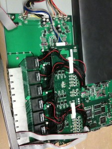
My latest switchmodding project is the silencing of a Netgear Smartswitch GS724TPS. This switch is the newest 24 port gigabit smartswitch of Netgear with Power over Ethernet (POE). The model got a powerful powersupply wich can hold an additional set of 120mm fans with cool LED’s. The switch got a factory set of 4 small Y.S.TECH FD124020EB 12V 0.12A 40mm fans. This 4 fans are responsable for an acoustic noise of 46 dBA. Ofcourse is this unacceptable within a home enviroment. I replaced the 4 small fans with a set of two Enermax Appolish 120mm fans 12V 0.4A fans. These fans got circular type LEDs up to 4 times brighter than any other. I choose the blue fans. |
 |
 |
 |
 |
 |
| The original fans are connected to the mainboard with a regular 12V 3-pin connector. The custom 120mm fans could be connected to these pins. Imported to know is the fact that the pins are reversed. The black wire is connected to the middle pin. This is different to standard computer-fans. However, I did not use this connectors because the fan speed is controlled by the mainboard. The current on the fans is between 7-12V. The LED-fans need a steady 12V so I used 12V of the mainboard-connector. Just use the white (+12V) en black (Gound) wires of this mainboard connector and you’re fine. (The yellow wire is a +5V).I cut two big wholes in the top of the switch. I also made a hole in the plastic of powersupply. I disabled the small fans by unconnecting the connectors of the mainboard. Note: This created a ‘fan-failure’ in the switchlog and the fan-error LED is lid, but who cares.. just ignore it. I also closed the fan-opening on the left side of the switch, so air can only be sucked in on the right side of the switch. This air cools all the components on the mainboard en powersupply. This is it.. A cool 24 port Gigabit POE switch suited for silent home networking. |
