HOME 

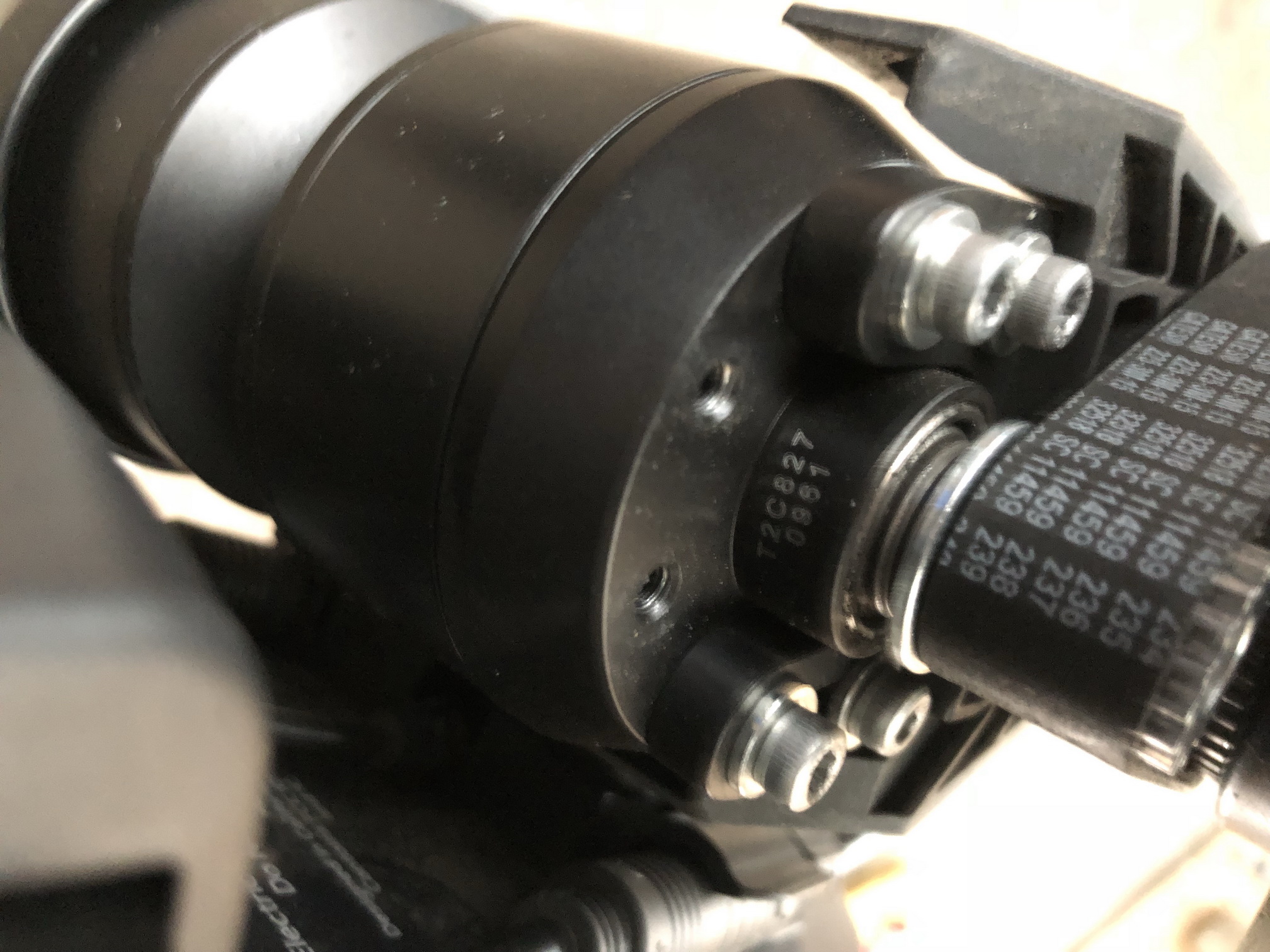
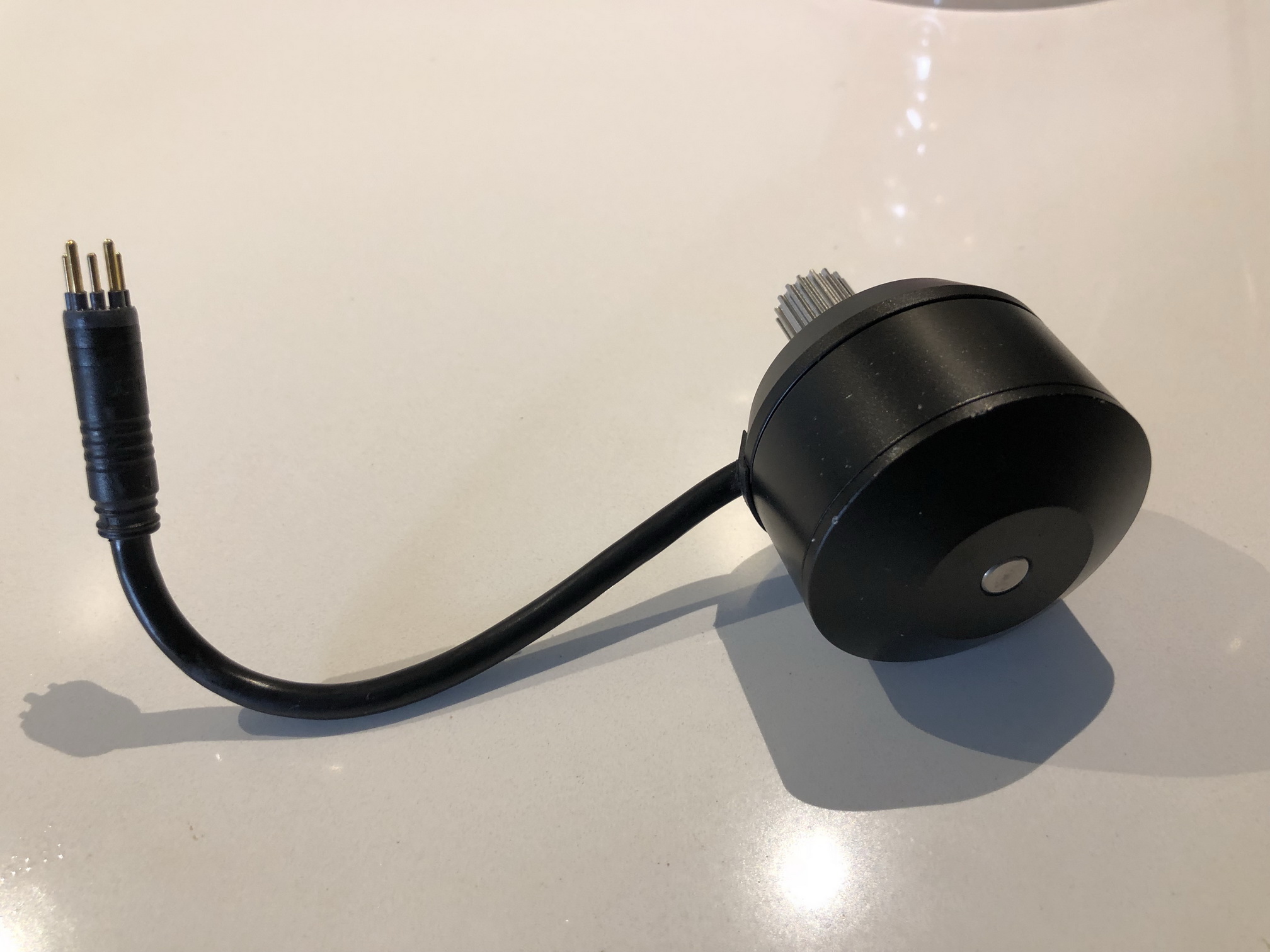
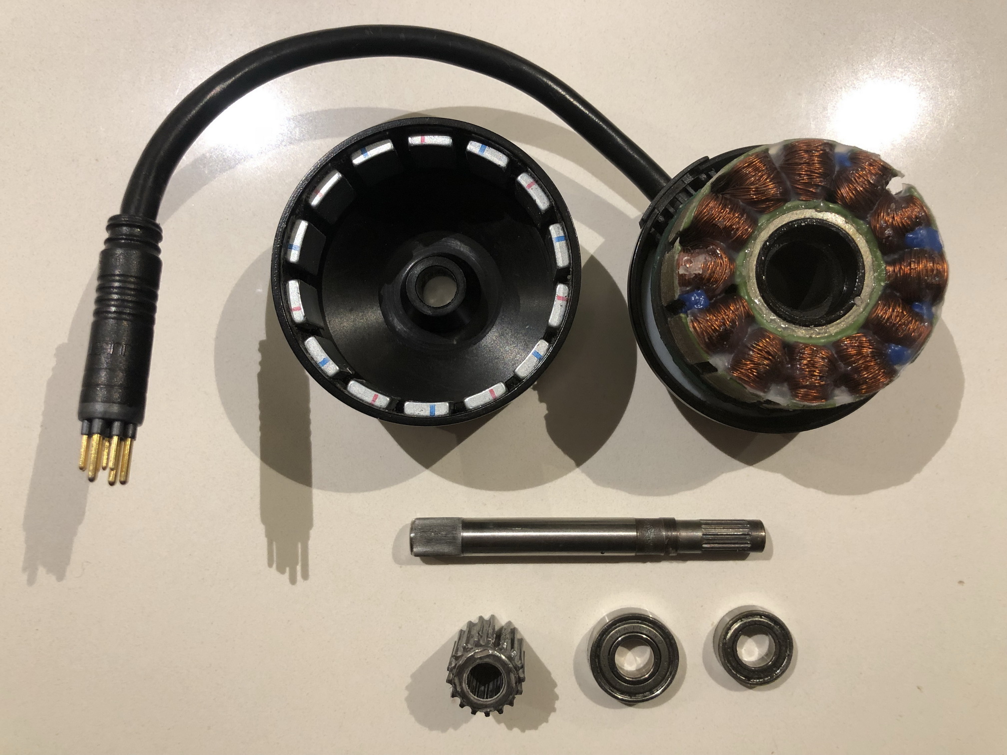
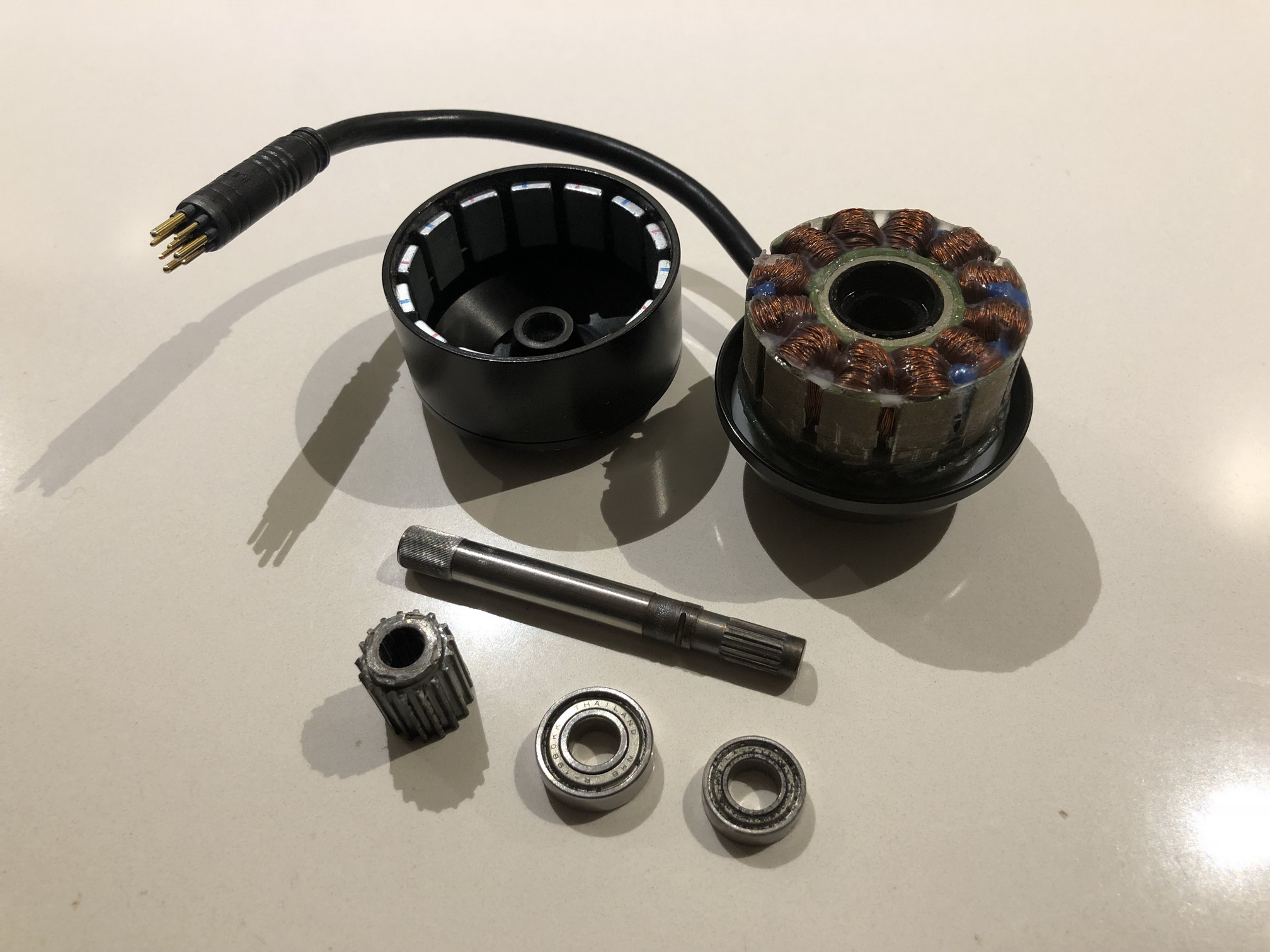
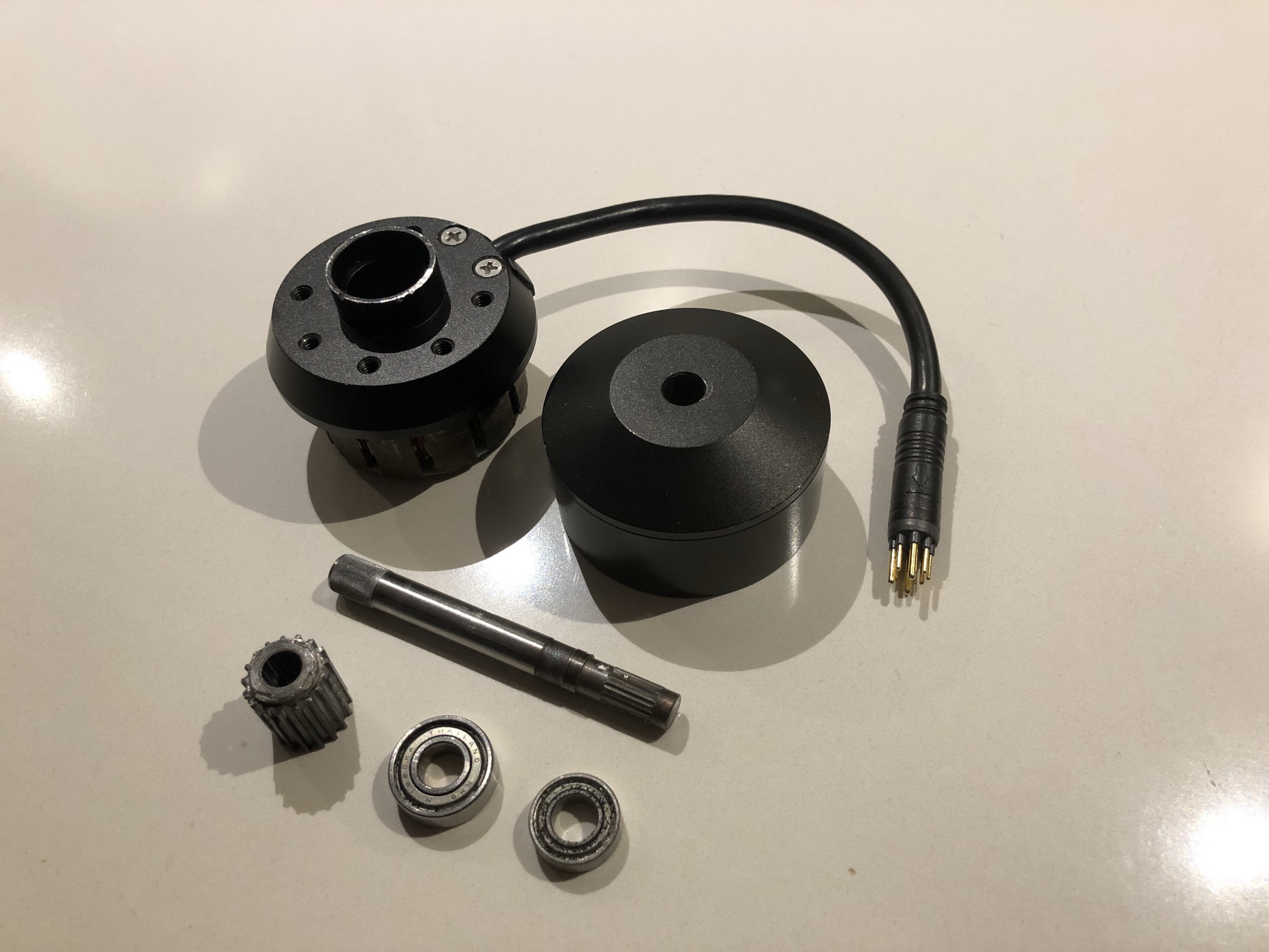
After experiencing problems with my Boosted Board Stealth motor, I wanted to know everything about the motor. There is some spacing between the shaft en the housing of the motor. In this video I explain what is causing this problem and how I repaired the motor.

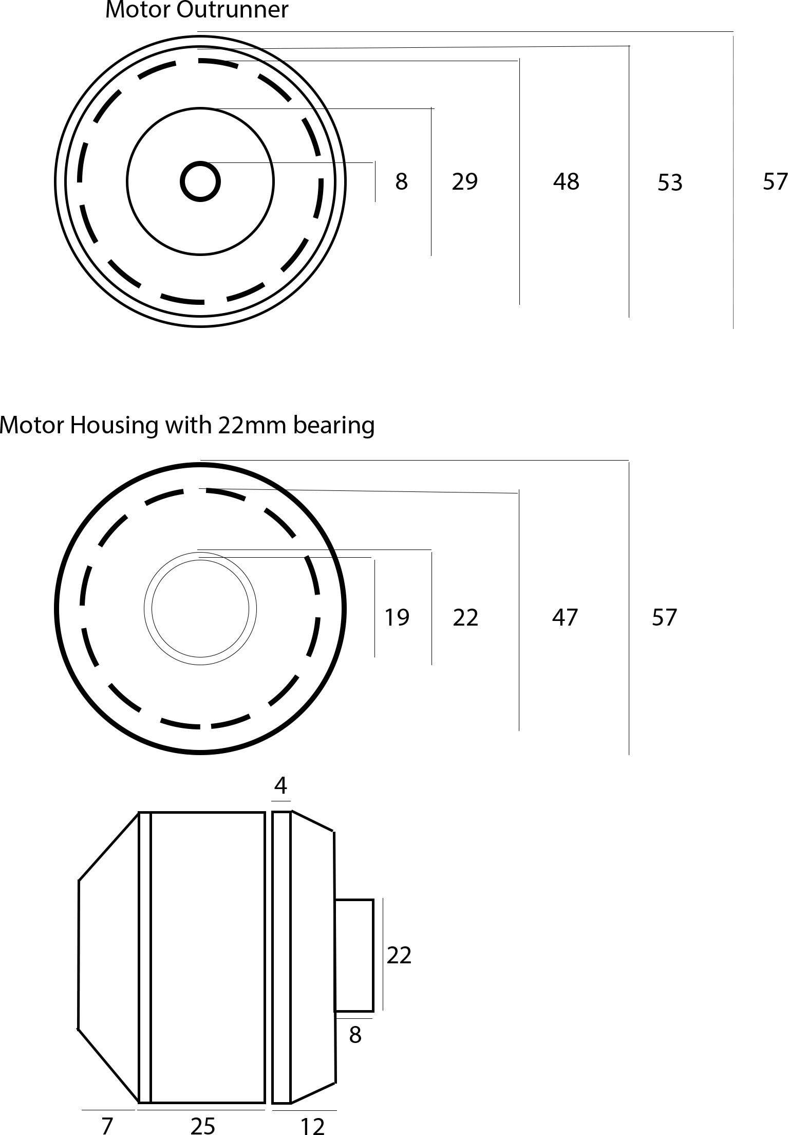
These are the dimensions of the new shaft I made:

After searching the web there is not much information available about the original motor. This is what I found out myself.
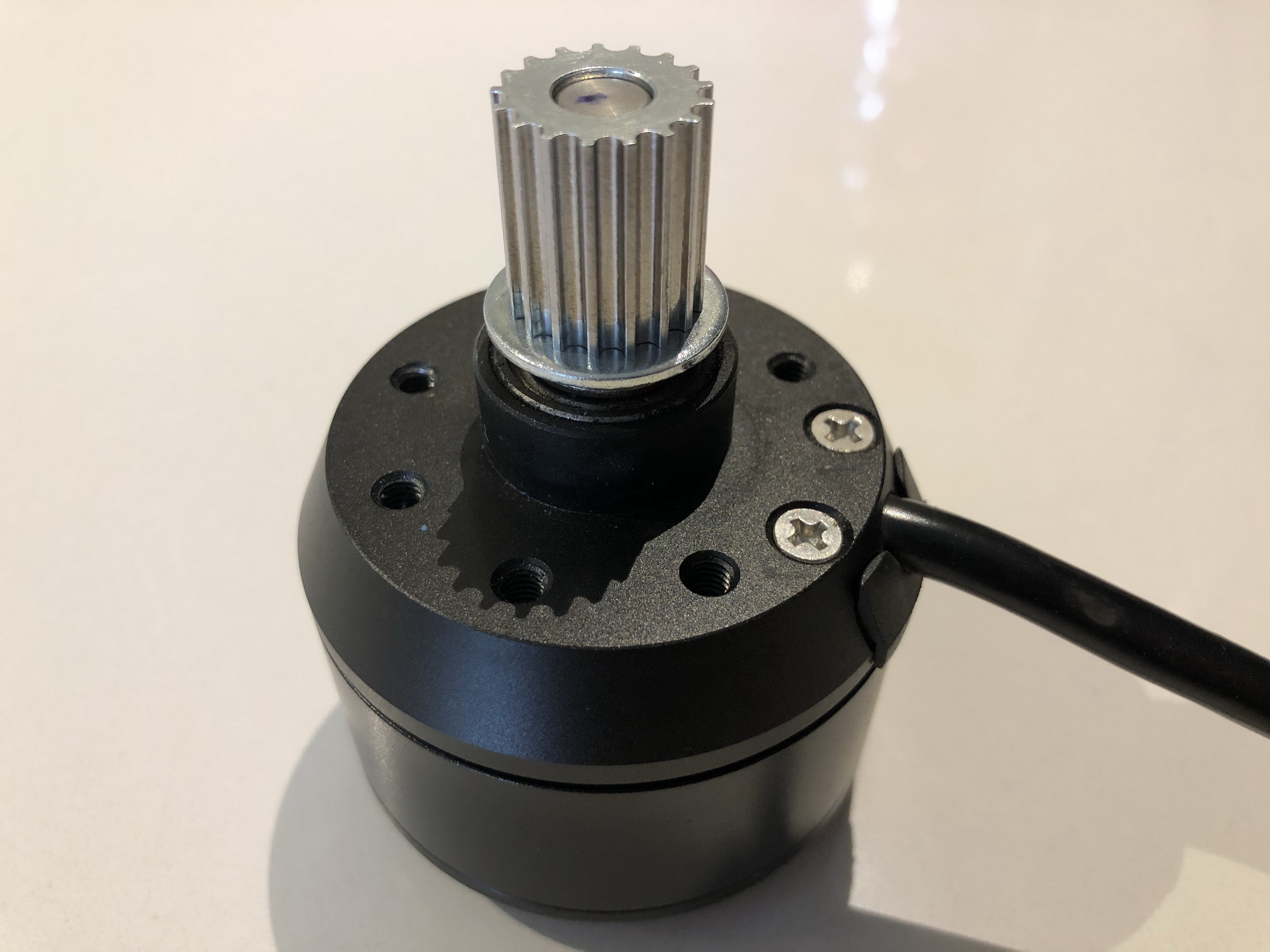
The connector of the motor is is of the type: Z910.  The Z910 plug is a popular one to find in lower power hub motors systems. It has 3 phase wire terminals good for about 30-40 amps of max current, the 5 hall sensor wires, and a 6th wire that is normally used as a wheel speed sensor in geared motors, or as a motor temperature sensor. Usually this is just called a “9 pin motor” or “waterproof motor” plug, which isn’t all that precise.

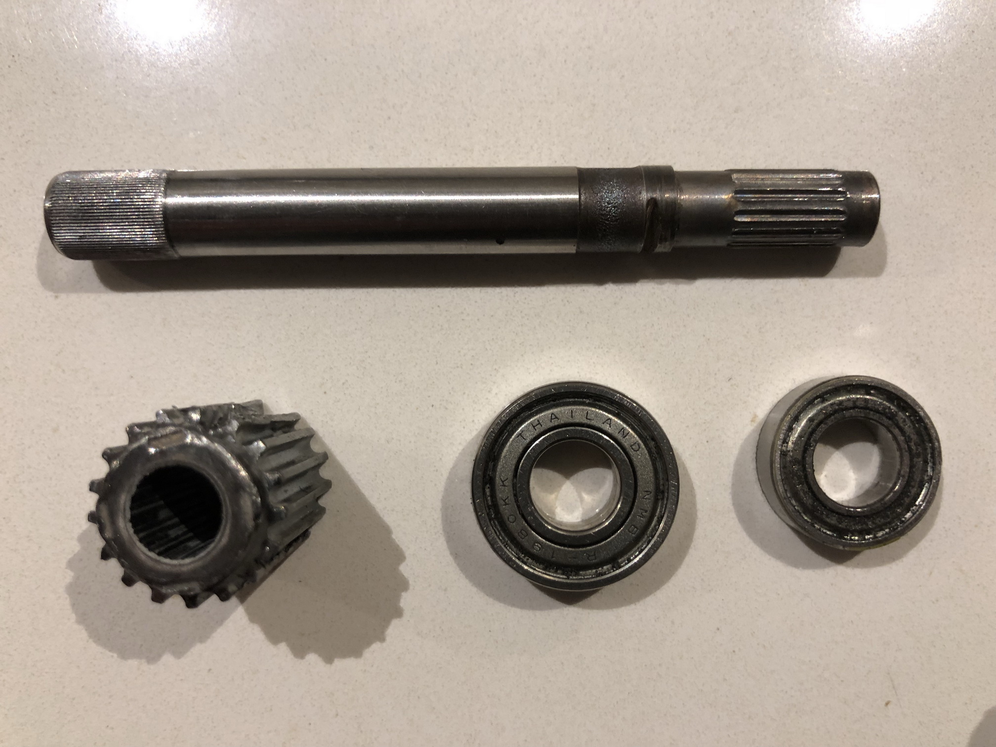
The original outside bearing is a NMB R-1980-KK with a dimension 8x19x6 mm.

The inside bearing is a NMB L-1680Kwith a dimension of 8x16x5 mm.
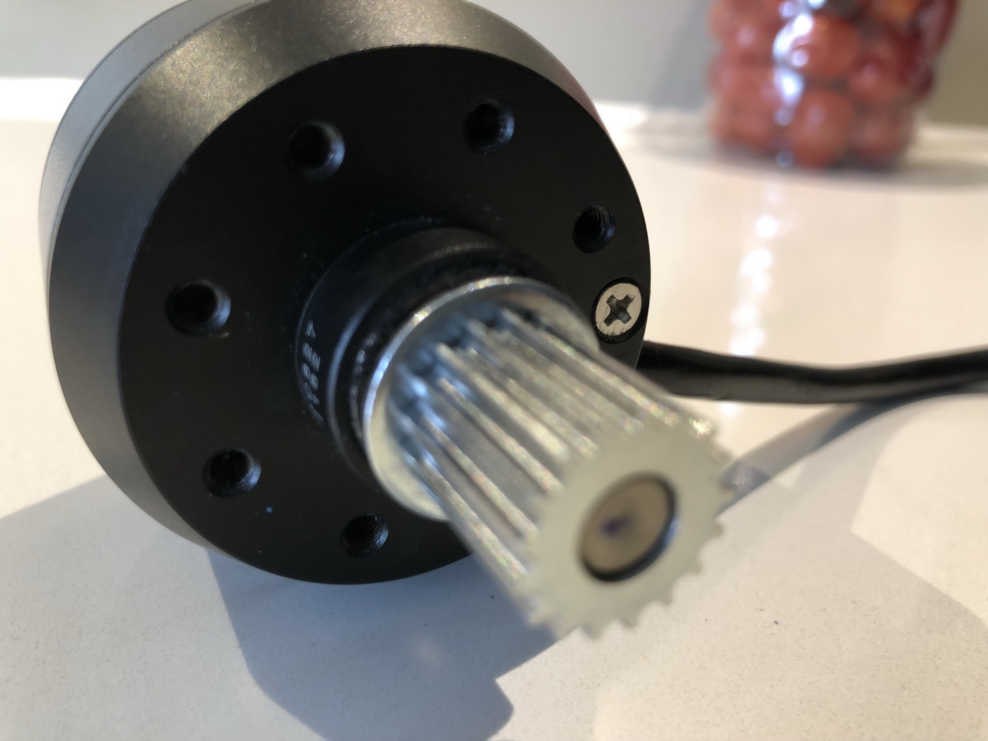
Manufactorer Boosted
Product number T2C827
Pinion width 15.5 mm
Pinion height 17 mm
Pinion teeth 17
Pinion incl washers 22 mm
Shaft length 75 mm
Shaft width 8 mm
Bearing pulley side 8x19x6 mm
Bearing top side 8x16x5 mm
Connector type Z910


For my Raspberry Pi burglar alarm project my goal was to connect my 12V PIR to the GPIO pins of my raspberry Pi. Of course the GPIO input pins can’t handle this kind of current, so the best way to do this is do isolate the circuits of the 12V PIR and the GPIO pins of the Pi. This is easily done with the use of an electronic component called “Octocoupler”. You can buy this components and make a board yourself or you can buy these boards online. This octo-isolator boards are somehow pretty expensive comparing to the switching relay port board for the Pi or Arduino. You can buy an 8 port relay module everywhere online for approximate 10 euro, but a 1 port octo-isolatorboard is in the price range of 100 euro. This is strange because the electronics are pretty much similar. Actually when you look at the relay board, it is even less complicated. I found out the the “common” relay board also got octocouplers besides the relays. This makes it possible to simple modify you cheap relay board and change it into a opto-isolator board by removing the relays and reuse the other components. Only some wire and two resistors are needed for every port.

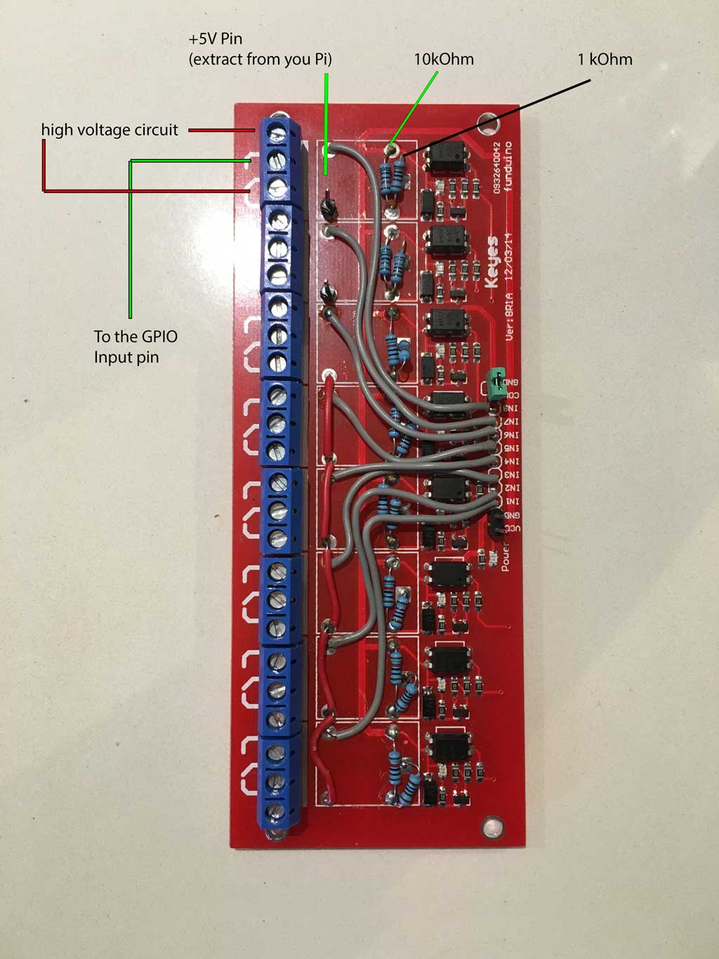
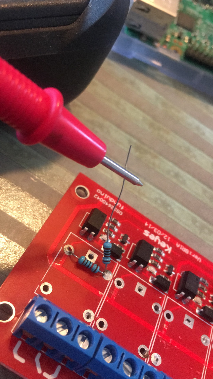
Take a good look at the two images and you know how to change the board. These are the steps:

  1. Remove the relays
  2. Remove the input pins from the board
  3. Solder the new 5V input pin. You can connect all the pins to supply every port with one connector.
  4. Solder a connection from the original input pin to one of the relay hole. Check image.
  5. Solder a 10 kOhm resistor shown in the image for every port
  6. Solder a 1 kOhm resistor shown in the image for every port

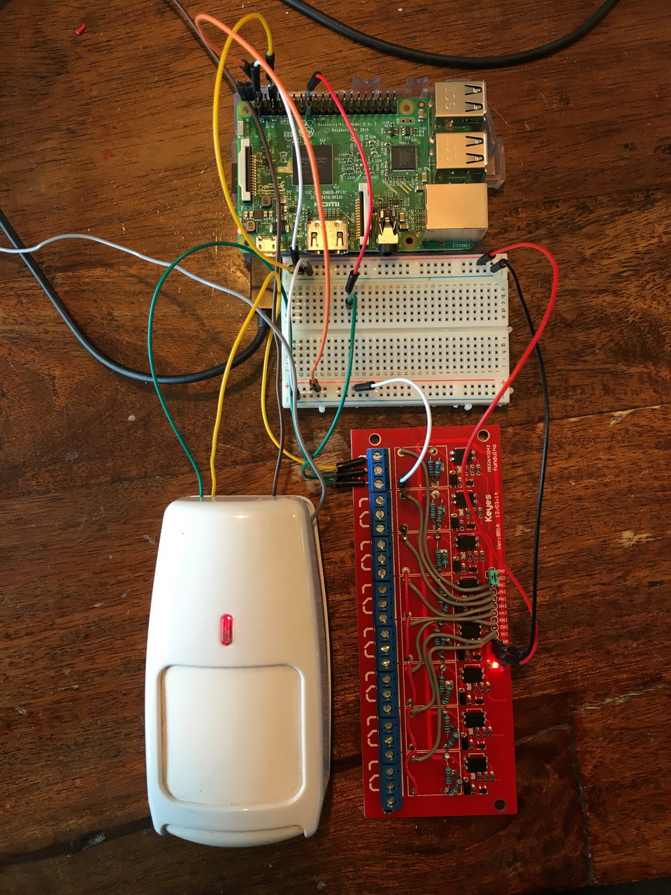
Thats it.. The 5V is switched by the octocoupler when for example a 12V current flows in the high voltage circuit. The can by measured by the GPIO pins. Remember that the board itself still needs to be powered with a 5-12V. Here is an example how to connect a 12V passive IR detector to the GPIO pins using the octo-isolator board:

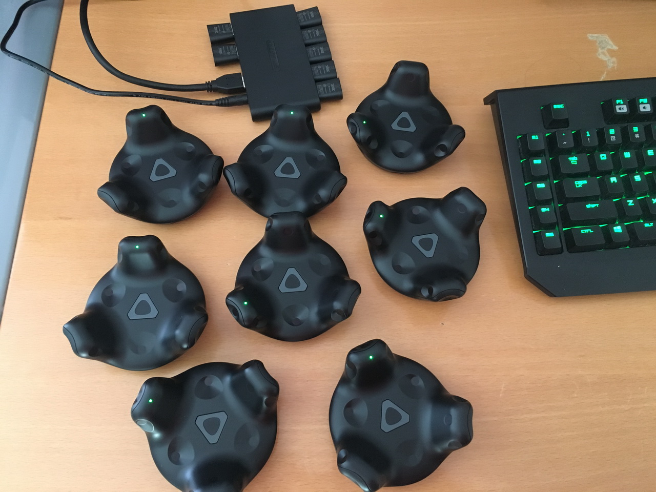
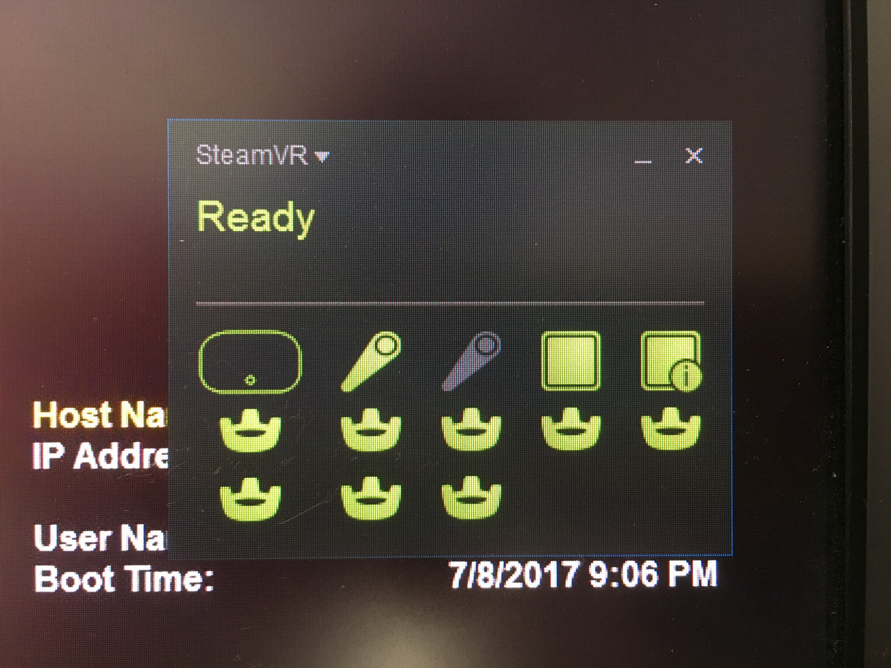
Finnaly I got my Vive trackers. I got 8 pieces of them. They are all detected in SteamVR and the installation is pretty straightforward. They do not have a texture in the Vive Home.

Save

I finally got my perception neuron 32 kit. This is a high tech cost effective wireless motion caption system. This system uses multiple sensors called neurons instead of the tradiction use of camera’s.
Check out my unboxing and review video.

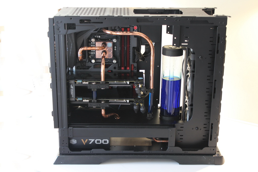
IMG_2036_resize Recently I have been busy building a new rig. It started of with the purchase of the new ASUS MAXIMUS VII FORMULA mainboard and a dual Geforce GTX780 DirectCUII OC. This mainboard got a hybrid chipset cooling so I decided to go with a watercooling system to cool this chipset and all the other component like the CPU and GPU.
To be able to mount all the watercooling components I needed to modify my casing. Especially the water reservoir needed a lot of space. I started of with my Coolermaster Stacker 831 case. The theme of the project is Black with copper based tubing. The result is awesome! Check out my buildlog of this project
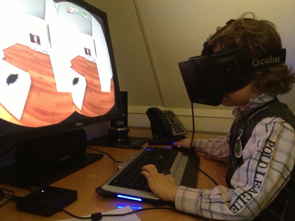
20131220-105016.jpg I bought te Oculus Rift development kit. Back in the 80th i wished i could own my own Virtual Reality system, and now the time is here. It’s “just” the early development kit of the Rift wich is still pretty low resolution (720p) but the experience is here. I registered myself as developer and i’m building my own house and living room within the Unreal development Kit (UDK) . There is more to come!The kids also enjoy this new virtual environment 🙂
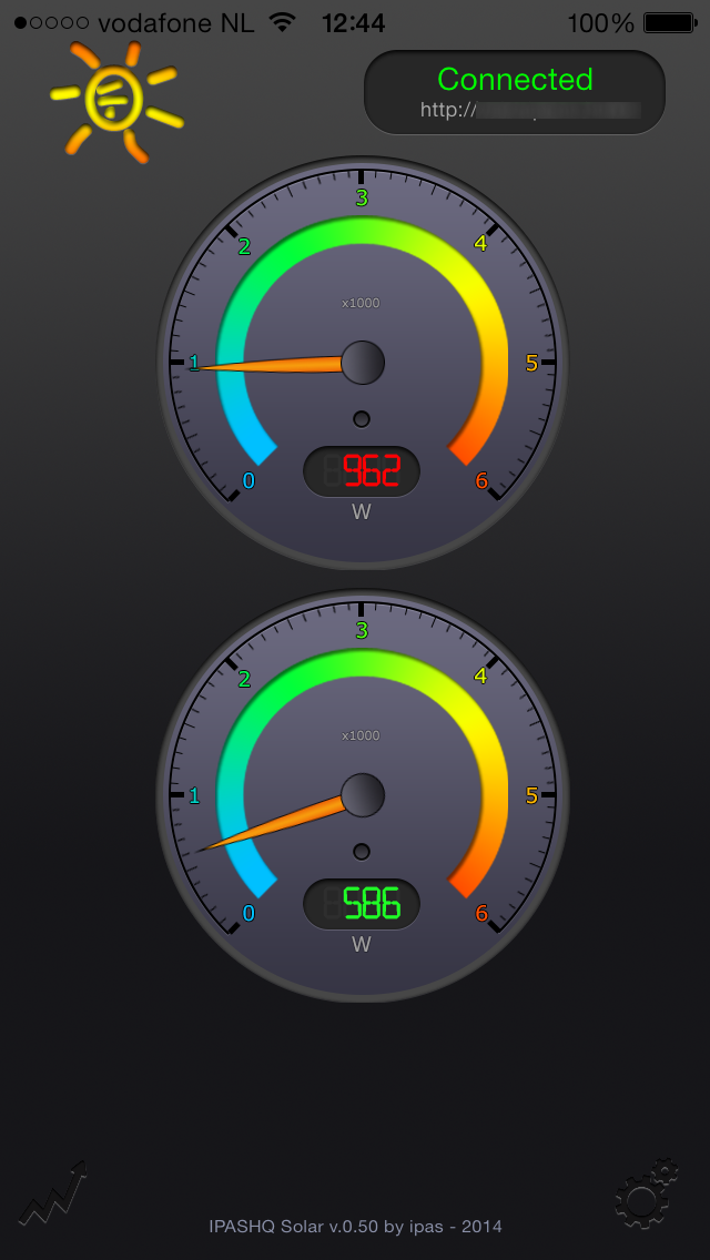
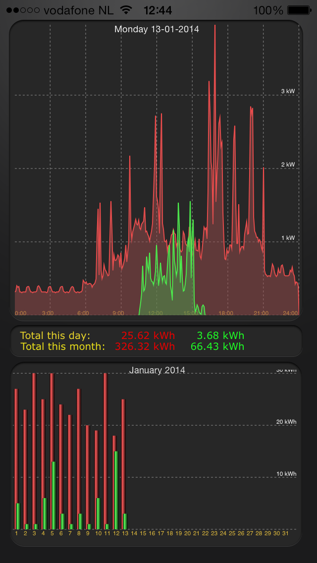
Solar.0.50.Screenshot2 Solar.0.50.Screenshot1 Version 0.50 of the solar app is ready. It took me some time to complete the software but finally it’s done. This version contains a monitoring of realtime statistics about the power usage and generated solarpower. The interval between the updates is 5 seconds or less. The app uses a websocket connection with the (raspberrypi) server running the solar server software.
The app also got functionality to display daily statistics of usage and solarpower in a 24 hour diagram. With a swipe it is possible to scroll between pages. The app connects with the webserver running a php/mysql system wich generates an xml containing the data.The application can be downloaded here.
20131107-153610 20131107-153636
20131107-153644 20131107-153826

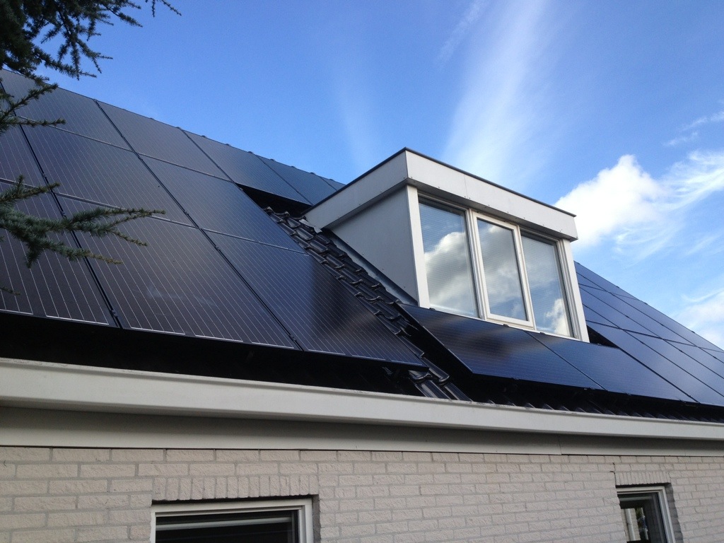
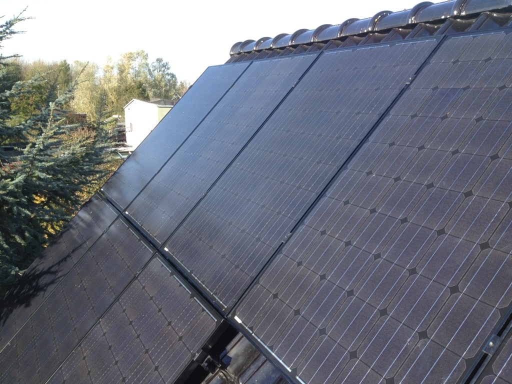
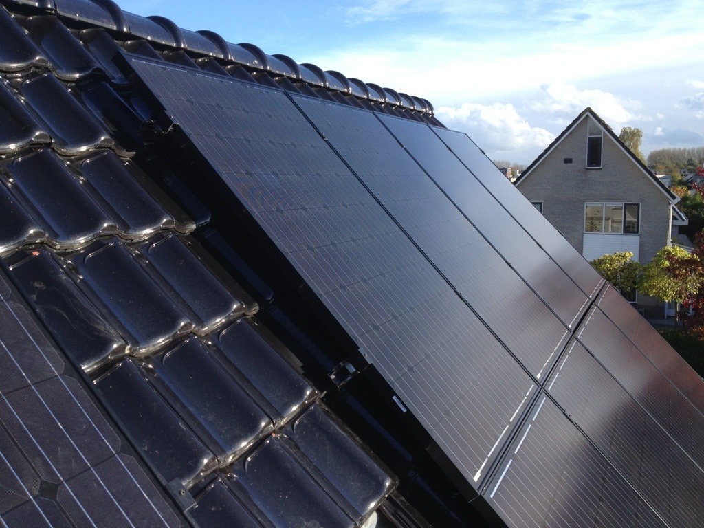
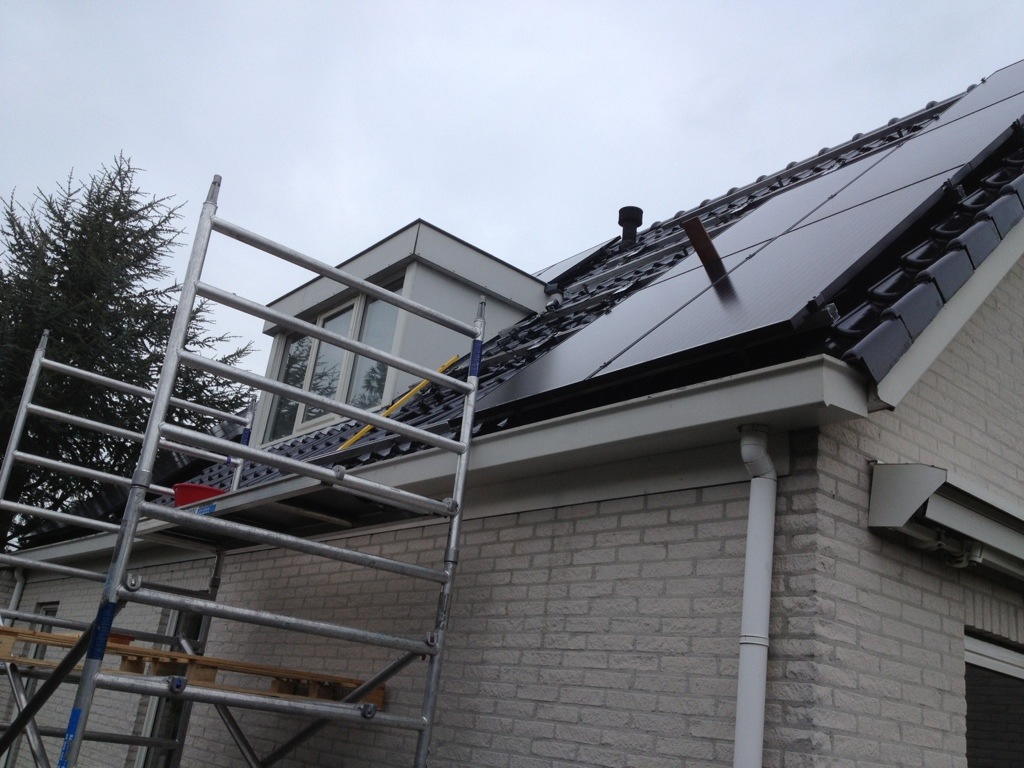
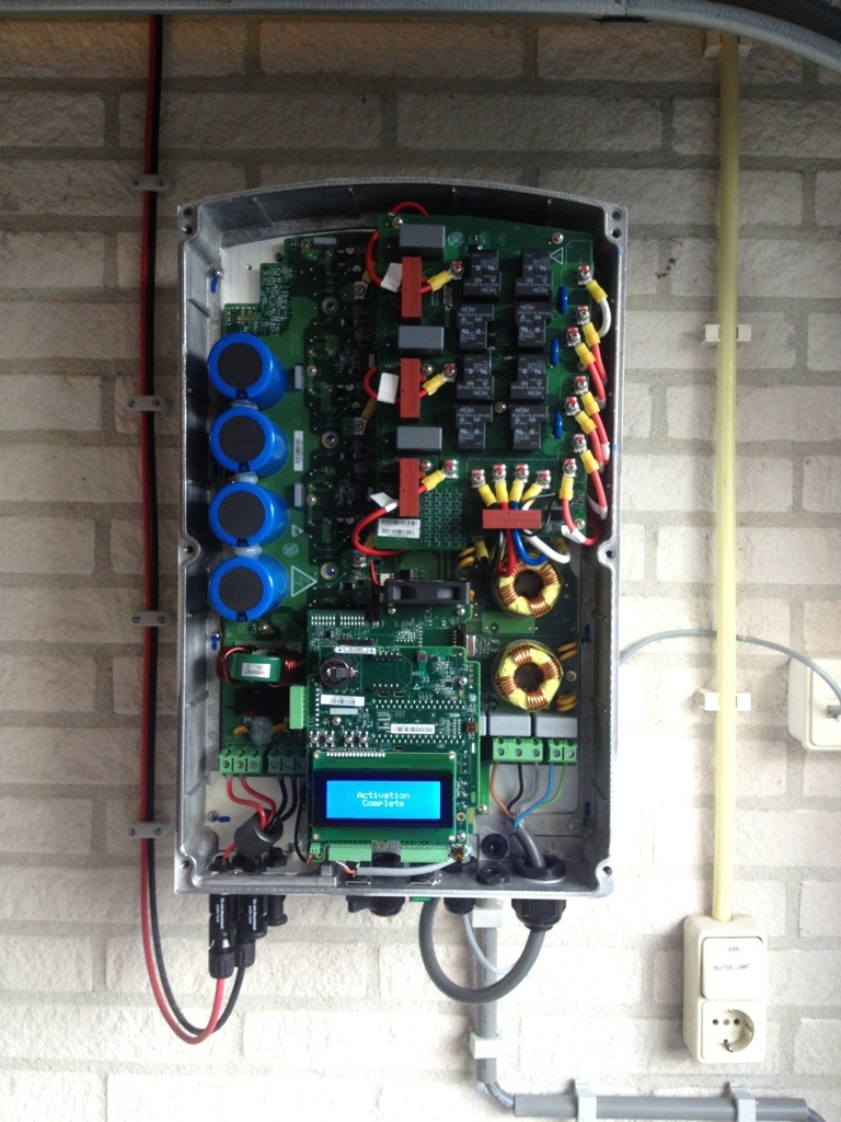
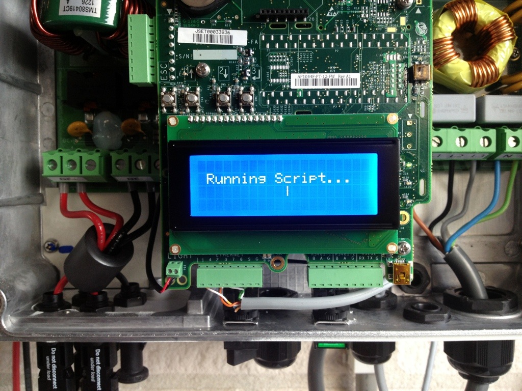
I finally placed the 30 solar panels. I installed 26 JA Solar 255 Wp panels on my tiled roof and 4 on my flat roof. In total i have a 7650 Wp system. The inverter is a SolarEdge Se7K.


20131109-190027 20131109-190056

This is a video of a labtest showing how to install a virtual shared graphics adapter in Vmware View 5.2. I use a Nvidia Quadro 4000 GPU on the ESX 5.1 host. This video shows how to install the Nvidia GPU vib drivers on esx and how to configure a desktop pool to use hardware based 3d rendering in Vmware Horizon View administrator.